


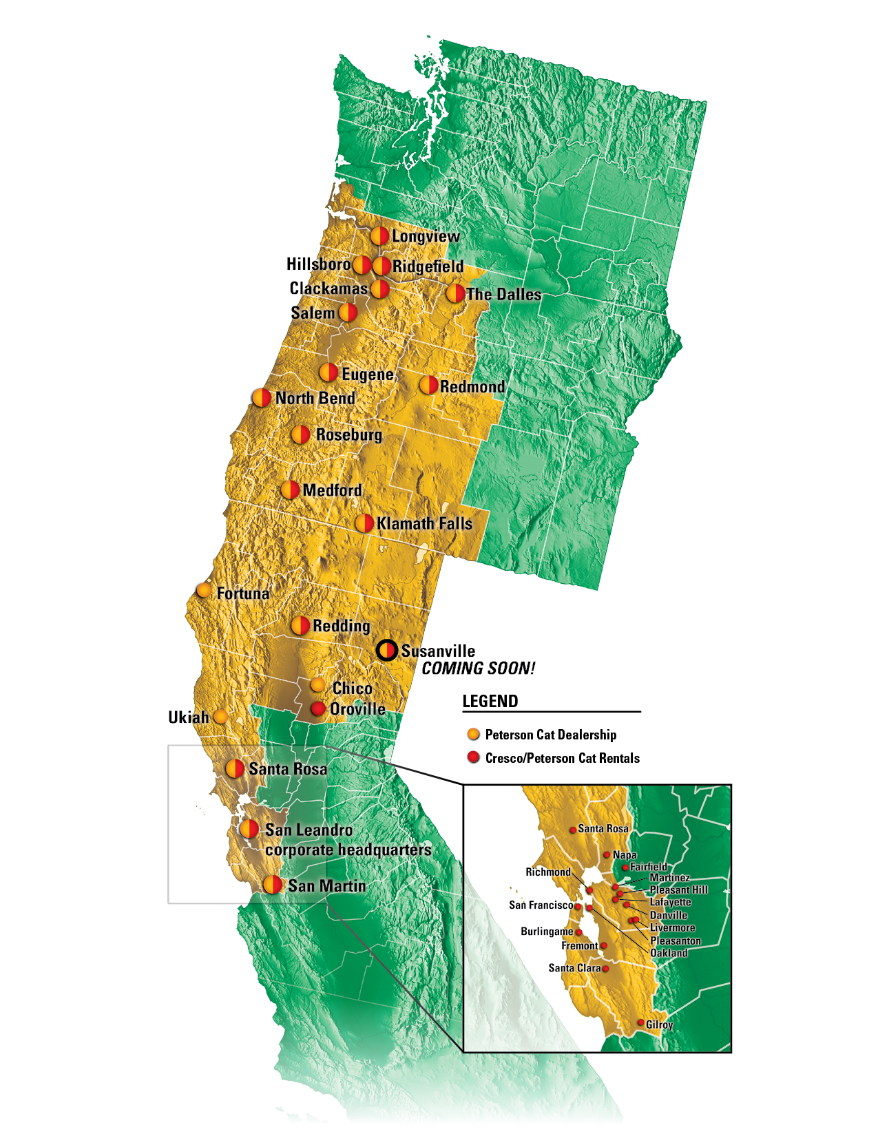
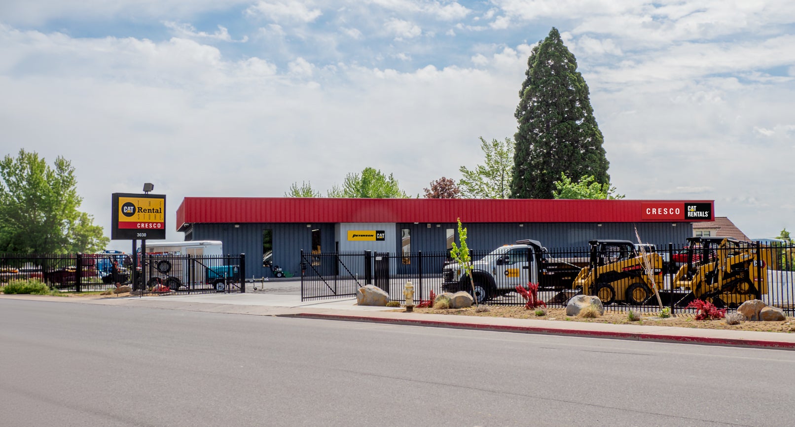
Now Open in Susanville!
Peterson Cat is Your Source for Genuine Cat Parts, Service, and Sales
Peterson Cat and Cresco Cat Rentals are open for business in Susanville as of June 15. We’re your source for Genuine Cat® Parts, equipment service, sales and rental!
3030 Riverside Dr
Susanville, CA 96130
530-240-9499
M-F 7am-5pm
STAY IN TOUCH!
Get the latest news and developments from Peterson Cat and Cresco Cat Rentals, including special offers, discounts, and information about our Susanville store’s grand opening!
Peterson Cat in the news!
Specials
Machine Financing Specials
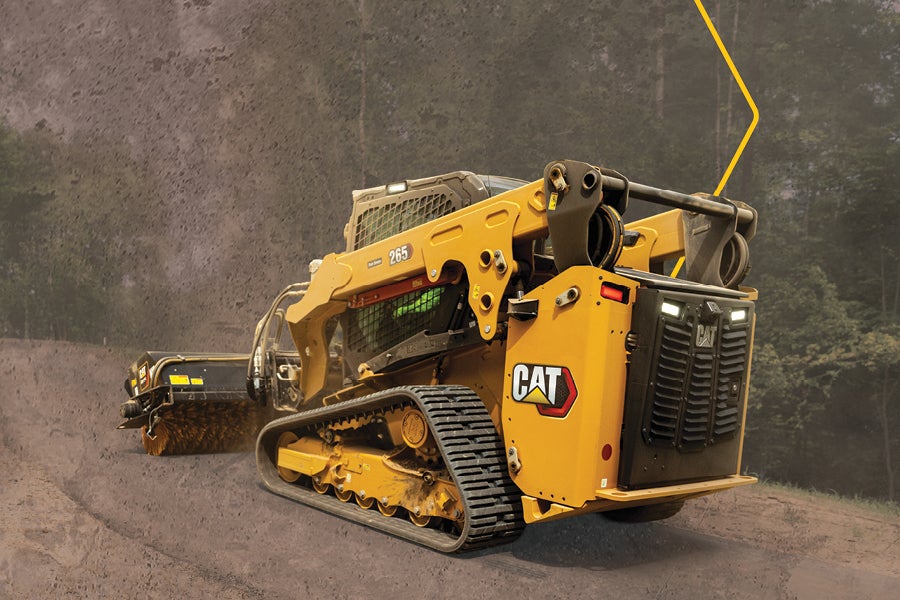
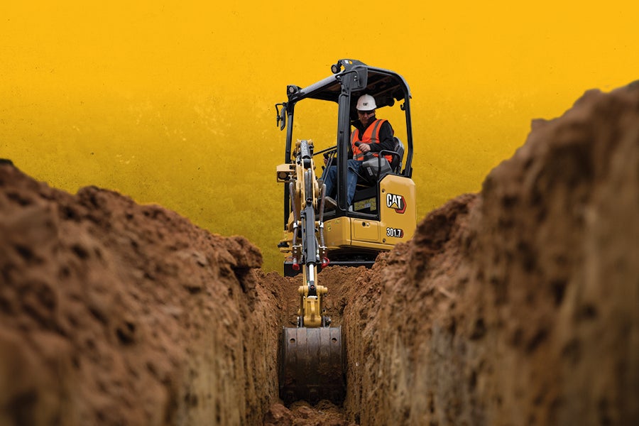
0% for 60 months
on new skid steers, compact track loaders, mini & micro excavators, and compact wheel loaders.

0% for 36 months
on new backhoe loaders, small wheel loaders, small dozers, and telehandlers.
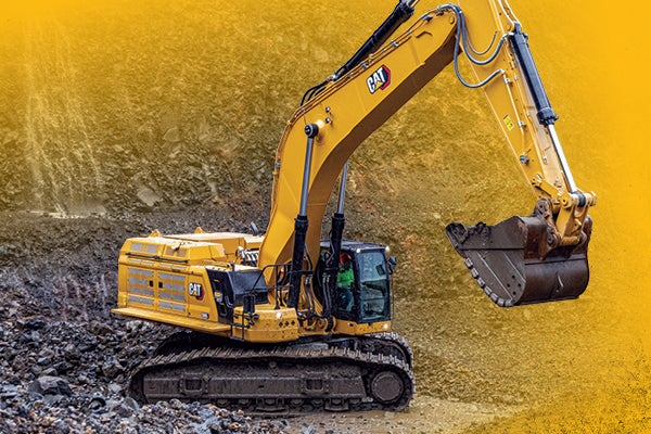
0% for 36 Months + CVA and EPP
on new 313-390 excavators includes Forestry Models!
0% for 36 Months + CVA
on new articulated trucks + small, medium, large and wheeled excavators.
3.99% for 48 Months + CVA
on new medium dozers, medium wheel loaders, track loaders, motor graders and soil compactors

0% for 18 Months
on qualifying Cat work tool attachments: augers, brooms, hammers, mulchers, and more!
Need help finding the best deal or selling your machine?
Contact us to discuss new, used, lease, and consignment options.
Parts & Service Specials
Bucket Rebuild Special:
35% off original GET parts ● 15% off labor ● Special pricing on plate (in-house rolled & fabricated)
0% for 36 Months with no payments for the first 6 months
on new and Cat Reman parts, with or without service. $3,500 minimum purchase.
Undercarriage Offer
Free inspection, 0% for 36 months, and no payments for 6 months. $3,500 minimum purchase.
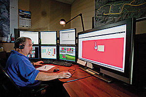
Want to manage your machines online?
Our eCustomer Support Team is happy to take your call, help you set up an account, and provide training.
 WARNING