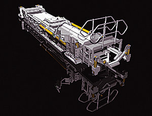
Engineered to Perfection
There are many parts to an Armored Face Conveyor: shearer haulage system, drives, drive frames and sprockets, gearboxes, line pans, chain conveyors as well as entry conveyors and belt tailpieces. Each of these components has to be engineered to perfection, but also has to work together optimally with the other parts of the system.
Shearer Haulage System
Cat rackbar shearer haulage systems meet the demands of today’s high-performance shearers. We use design and material selection aimed at achieving maximum system availability, longest possible shearer, sprocket and trapping shoe life and on-system suitability for seam undulations.
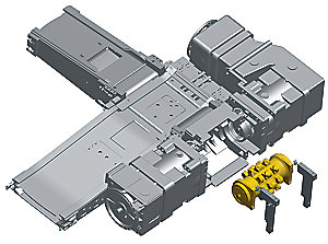
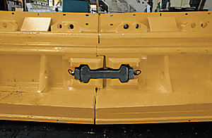
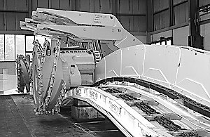
Drive Frames
Head-gate drive frames operated today are typical of the cross-frame design. Different capacity ratings are available depending on the total power required. The frame sides are manufactured from thick, solid plates to handle the high torque that may be generated and to ensure an adequate safety margin. Flange plates used to mount the transmission units enable easy rehanding.
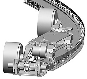
Drive Modules
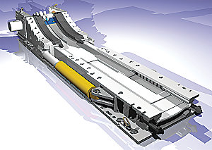
The latest development is a drive frame with replaceable one-piece sprocket/shaft/bearing - a “drive module.” These are available in various sizes to suit individual power requirements, right up to 2 × 1800 kW (2,412 hp) per drive. The drive module is identical for both main and tail drive. The drive frames are independent of the gearboxes used - flange plates and stub shafts are used for interfacing. Two hydraulic cylinders are integrated in the frames for disassembly of the drive module. These are powered by an external pump. There are similar designs for smaller drive frames.
GR Sprocket
In contrast to conventional sprockets, the Cat GR sprocket is specially designed to spread the load across three teeth, ensuring maximum contact surface between the chain links and the sprocket teeth during operation. This results in lower wear and extended life of the sprocket and the chain.
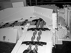
Tail Drives
Tail drives are normally the tensionable type, especially with long faces and/or high installed power. These have a stroke of 0.50 m for shorter, less powerful conveyors, and 1 m for long faces or conveyors with extremely high installed power. These allow control of 1 m and 2 m of slack chain respectively. An automated system keeps the AFC chain at optimum tension during operation.
Gearboxes
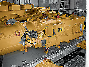
Caterpillar offers gearbox solutions - simple planetary or bevel-spur gearboxes for low-power requirements and the installation of a clutch between motor and gearbox for medium-power installations.
Overload Protection
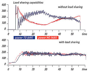
Overload protection is achieved by measuring the slip of each gearbox. In the event of a chain stall, both motors are switched off. Alternatively, the clutches at both drives can be opened using an optional drive control unit. The Controlled Start Transmission (CST) drive system is designed for long, high-capacity faces. This drive system allows no-load motor startup, synchronized soft-start and heavy-load startup, as well as accurate load sharing and excellent overload protection.
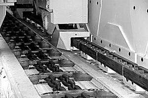
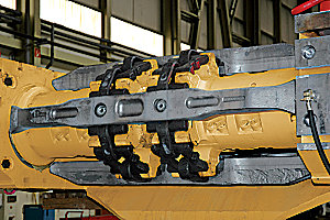
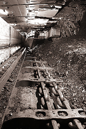
Chains
For years, we have been matching chain and sprocket design in high-performance face conveyors to achieve optimum performance and service life. This resulted in the 42 × 146 mm (1.70 × 5.70 in) combination chain, the standard chain for applications in the USA and Australia since 1991, and later in the 48 × 144/160 mm (1.90 × 5.70/6.30 in) chain for what was then the world’s most powerful conveyor installation with 3 × 1000 kW (3 × 1,341 hp) on a single longwall face conveyor.
PowerChain
The wide, arc-shaped cross-section of the vertical links allows a low-profile line pan and the special shape of the horizontal link provides a large running surface where required, drastically reducing surface pressure and chain-joint wear. The method for attaching the flight bar is patented. The PowerChain 42 × 140 mm (1.7 × 5.5 in) has a breaking force of 2370 kN, the PowerChain 52 × 175 mm (2.0 × 6.9 in) of 3610 kN.
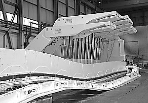
Entry Conveyors and Belt Tailpieces
Entry conveyor or stage loader pans are normally of the same type as used in the face. These are normally wider than the AFC. While the return roller is integrated into the cross frame design, the head drive frame of the stage loader is tensionable using hydraulic cylinders. The crusher, usually an impact roller, is integrated into the stage loader design. The following goose-neck lifts the stage loader discharge over the belt tail piece. Belt tail pieces are available in fixed-, skid- or crawler-mounted versions with an overlap of up to 3.5 m (11.5 ft), all equipped with self-cleaning return drums. The operator can use any specified belt width in this tailor-made equipment.
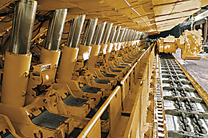
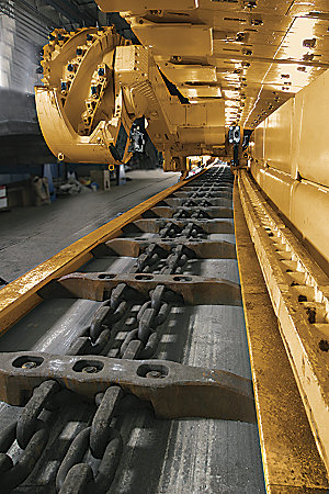
Line Pans for Every Need
Rolled steel is smoother, stronger and harder-wearing than a casting and generates less friction and noise.
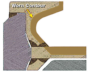
Maximum Contact
The profiles are designed to maximize the contact area between the flight bar and the profile, thus minimizing contact pressure during operation.
Rolled Steel
Rolled material has a smoother surface than castings. The material shows maximum wear resistance after initial material conveyance.
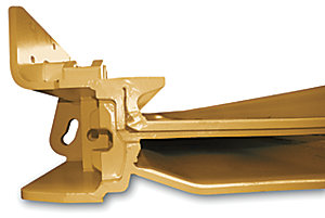
Safe Dogbone Technology
The forged dogbone pocket and the designed breaking force of up to 4500 kN guarantee safe operation of the conveyor at all times. Sophisticated design has been further optimized, ensuring greater tensile strength to reduce stress spikes and ensure perfect protection of the dogbone pocket and the pan itself in the event of an overload.
Convex/Concave Pan Ends
Cat line pans feature convex/concave pan ends that ensure reduced noise levels.
Welds without Wear
Cat PF line pans have a rolled profile design. Each of the identical profiles are attached with two welds to the top plate of chosen length and width. This results in great flexibility in pan design. Only one of the welds is located in the wear area of the line pan in the top strand.
Wear-resistant Top Plate
The top plate is made of wear-resistant material. The thickness varies from 30 mm (1.2 in) (PF3) to 50 mm (2.0 in) (PF5).
Flexibility
The line pans are designed to allow deflection between individual line pans of ± 6° vertically and 0.8-1.2° horizontally.
Safe Transfer of Transverse Forces
Transverse forces are transferred through the top plate to the relay bar arrangement.
Inspection Doors
A sliding inspection door typically installed in every 6th pan and every special pan allows access to the bottom race of the chain conveyor. The integrated drawer guide ensures safe seating of the doors. The inspection door can be removed from gob or face side.
Separation of Wear Parts and Structural Parts
The smart and totally new idea of splitting up the different functional areas in the PF6 allows the separation of wear parts and structural parts. Very hard, wear-resistant materials are used for wear parts, while the structural parts are made of high-strength steel.
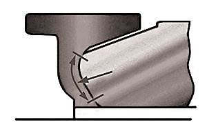
Optimized Contact Surfaces
The special shaping of the bottom race - which almost doubles the contact surface - reduces flightbar shoulder wear and substantially reduces friction. The curved transition at the pan ends greatly reduces noise during operation of the chain conveyor.
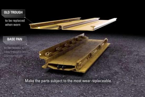
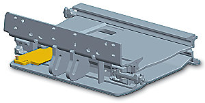
Maximum Pan Stability
The frame of the pan consists of two C profiles connected by a baseplate. Two tried-and-tested PF5 profiles are welded to the bottom plate of the top trough and then welded or bolted to the pan base. This allows problem-free replacement of worn top troughs. Pan sections are connected by dogbones inserted into pockets in the C profiles. These are designed to engage exactly, providing optimal absorption of vertical and horizontal reaction forces. This ensures reliable transmission of high lateral forces, such as from roof supports. All forces were calculated and the pan was successfully tested with the frame of the PF6 pan only.
Customization
Whether the design of the cover plates or the design of spill plates for hoses and cables, all components of the PF6 are individually designed to meet our customers’ requirements.
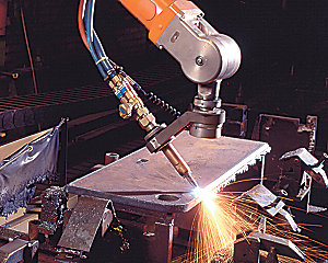
Rolled Steel Surfaces and Robot Welding
Extremely smooth rolled-steel surfaces ensure minimum friction and power loss. Robot welding ensures standardized welds that can be removed automatically when the top race is worn, allowing replacement of the trough. This innovation is expected to increase the service life of the substructure by a factor of 3.


 WARNING