


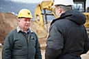


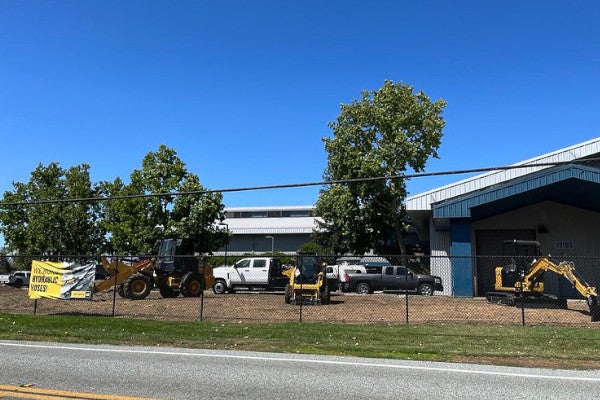
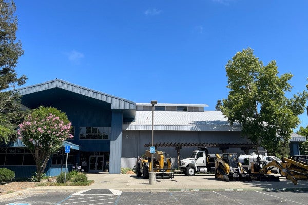
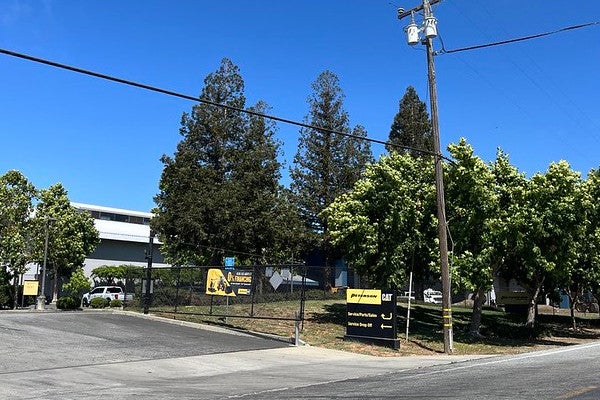
Peterson San Martin, California
Store Contact Info
13155 Sycamore Ave
San Martin, CA 95046
Main: 408-686-1195
Monday–Friday, 7:00 a.m.–4:30 p.m.
Parts: 408-686-1195
Monday–Friday, 7:00 a.m.–4:30 p.m.
Service: 408-686-1195
Monday–Friday, 7:00 a.m.–4:30 p.m.
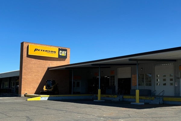
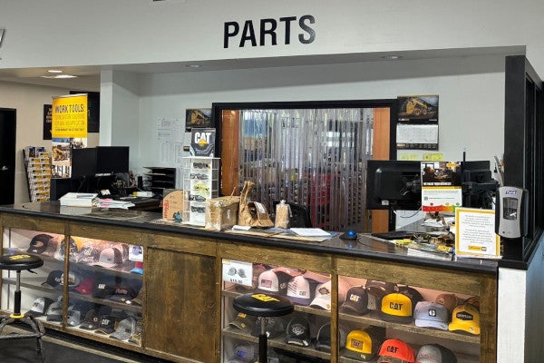
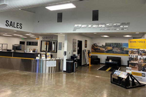
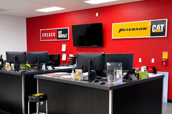
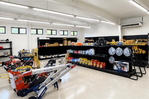
Images of Peterson Cat San Martin, California
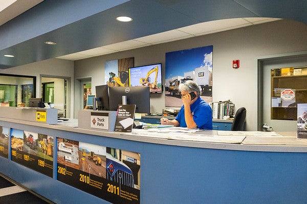
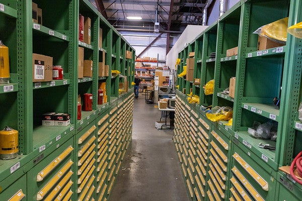
San Martin Cat parts warehouse
Peterson Chico, California
Store Contact Info
425 Southgate Ave
Chico, CA 95928
Main: 530-343-1911
Monday–Friday, 7:00 a.m.–5:00 p.m.
Parts: 530-343-1911
Monday–Friday, 7:00 a.m.–5:00 p.m.
Service: 530-343-1911
Monday–Friday, 7:00 a.m.–5:00 p.m.
Cat Parts, Service, and Equipment Sales in Chico
Peterson Cat Chico provides local support for Cat machines, engines, trucks, and equipment used in forestry, construction, agriculture, site development, road work, trucking, and public works. Customers can visit the Chico store for parts, hydraulic hoses, shop repairs, truck service, or schedule field service when machines need maintenance or repairs on the jobsite.
Our onsite parts warehouse helps customers get the Cat parts, fluids, filters, ground engaging tools, and maintenance items they need to keep equipment working. Our shop and field technicians support customers across the region with diagnostics, repairs, preventive maintenance, and machine service.
Cresco Cat Rentals in Oroville serves contractors, large and small, with all the tools and equipment they need for both commercial and residential projects. Popular items include boom lifts, telehandlers, Toro Dingos, and light towers.
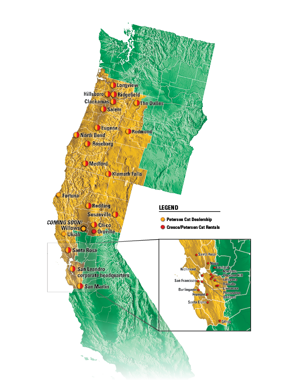
Serving Chico, Oroville, Willows, Quincy, Marysville, and Northern California
From farms and orchards to logging roads, construction sites, public infrastructure, and highway work, Peterson Cat supports the equipment needs of Northern California. Our location on Highway 99 gives customers convenient access to parts, service, and support throughout the Chico area and surrounding communities.
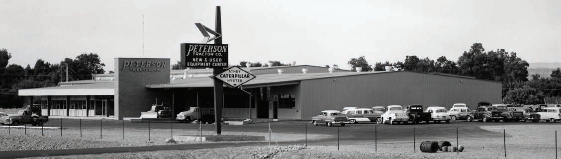
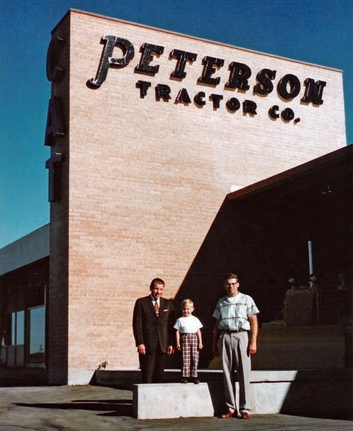
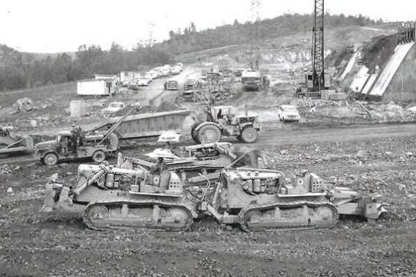
A Peterson History Connected to the Oroville Dam
Peterson opened for business in Chico in July 1958 to support construction of the Oroville Dam. The project used a number of custom-built machines, including Quad D9s, a special dual 631 compactor, and customized 100-ton Athey bottom dumps. These machines were designed and patented by Buster Peterson to meet the demands of one of California's largest earthmoving projects.
That legacy of problem-solving continues today. Custom design and fabrication are still available through Peterson's San Leandro, California and Hillsboro, Oregon headquarters.
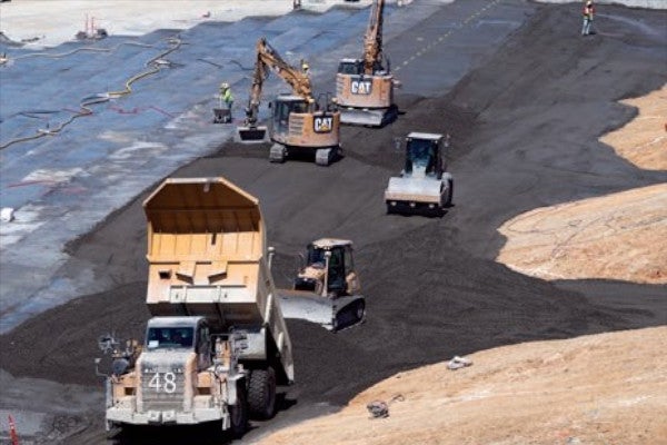
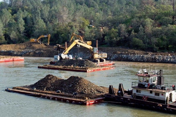
Supporting the Oroville Dam Spillway Recovery
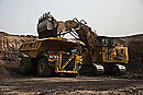
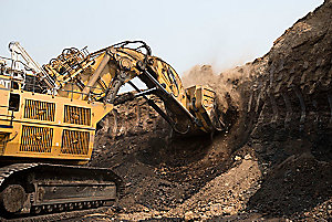
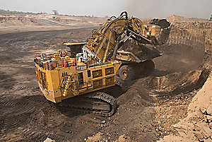
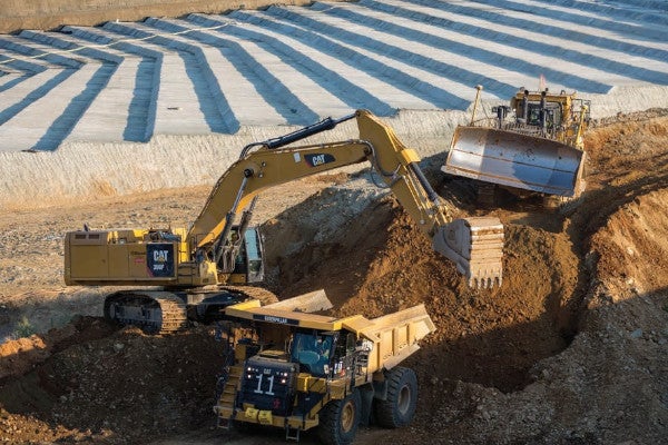
In February 2017, the Oroville Dam emergency spillway was used for the first time. After the hillside sustained major erosion, crews placed temporary rock and riprap as an emergency measure. Once the immediate crisis passed, Kiewit removed the temporary repairs and excavated down to bedrock as part of the recovery project.
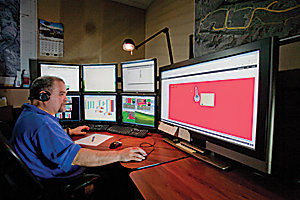
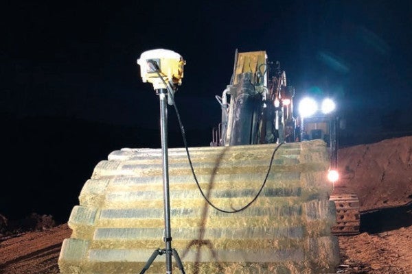
Peterson supported the project with machine control guidance systems and project management tools that helped Kiewit work quickly and accurately under tight deadlines. In the planning stages, Kiewit used specialized software to digitize original 1960s plans from the California Department of Water Resources and compare them with current drone data from the site.
Chris Mata, Peterson's machine control sales representative, explained the impact of the technology: "A project of this magnitude would take three to four grade-setters multiple days to complete an as-built topographic map of the surface. But Kiewit's drone allowed one person to do it in 30 minutes and provided real-time volume quantities and progress updates for managing the site."
Trimble machine control technology is still available through SITECH NorCal.
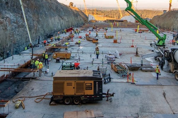
Power Generation Support for Major Projects
Peterson also supported the Oroville Dam work with generators. The site operated like a small city roughly 30 miles from Chico, requiring temporary power for offices, air conditioning, computers, light towers, batch plants, pneumatic tools, and other critical jobsite needs.
Electric power generation and temperature control solutions are still available through Peterson Power Systems.
Frequently Asked Questions
Where is Peterson Cat in Chico?
Peterson Cat Chico is located at 425 Southgate Ave, Chico, CA 95928, near Highway 99.
What are the hours for Peterson Cat Chico?
Peterson Cat Chico is open Monday through Friday from 7:00 a.m. to 5:00 p.m.
What services are available at Peterson Cat Chico?
The Chico location offers machine sales, genuine Cat parts, equipment service, field service, on-highway truck service, and hydraulic hose manufacturing.
Does Peterson Cat Chico serve Oroville?
Yes. Peterson Cat Chico serves customers in Chico, Oroville, Willows, Quincy, Marysville, and surrounding Northern California communities.
Can I buy new or used equipment from the Chico location?
Yes. Peterson Cat offers new and used machines connected to the Chico location, skid steer loaders, hydraulic excavators, motor graders, wheel loaders, and work tool attachments. Special finance rates are often available.
Peterson Susanville, California
You're invited to a Grand Opening Celebration & Open House
Please join Peterson Cat and Cresco Cat Rentals in Susanville on Friday, August 7, 2026
Friday, August 7, 2026 from 11 a.m. – 2 p.m.
(Complimentary lunch served at noon)
Peterson Cat / Cresco Cat Rentals
3030 Riverside Dr | Susanville, CA 96130 | 530-240-9499
RSVP Here:
Peterson Cat and Cresco Cat Rentals invite you to our facility in Susanville on Friday, August 7, 2026 from 11 a.m. till 2 p.m. We’re now your authorized Cat® Dealer and source for new and used machine sales, equipment service, Genuine Cat Parts, and rental equipment for any project for homeowners and contractors! Please join us to meet our local staff and corporate management, explore our facility, and enjoy a free lunch!
Store Contact Info
3030 Riverside Dr
Susanville, CA 96130
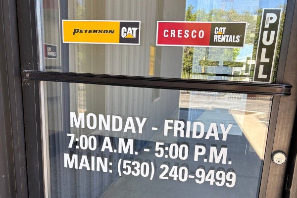
Main: 530-240-9499
Monday–Friday, 7:00 a.m.–5:00 p.m.
Rental: 530-240-9499 option 1
Monday–Friday, 7:00 a.m.–5:00 p.m.
Parts: 530-240-9499 option 2
Monday–Friday, 7:00 a.m.–5:00 p.m.
Peterson Cat and Cresco Cat Rentals operate in the same Susanville, California location to support loggers, contractors, municipalities, landscapers, ranchers, and equipment owners in and around Lassen and Plumas counties with new and used Cat machine sales, equipment rentals, parts, and field service.
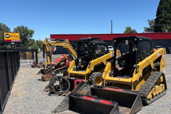
Cresco Cat Rentals
Cresco Cat Rentals in Susanville delivers equipment rentals backed by local support, Cat dealer resources, and a history of serving northern California. Popular rental items include scissor and boom lifts, lawn and landscape equipment, and concrete equipment.
We also rent the complete line of Cat construction equipment including mini excavators, skid steer loaders, wheel loaders, and telehandlers, as well as hydro-mechanical worktool attachments like hydraulic hammers, augers, and grapple rakes.
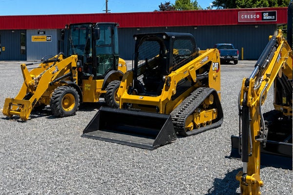
Peterson Cat Sales, Parts, and Service
Peterson Cat in Susanville offers new and used equipment for sale with special financing offers through Cat Financial. Machines can be sold from on-the-ground inventory, brought in from other Peterson locations, or ordered from Caterpillar to your exact specifications.
Peterson's $33 million+ parts inventory—combined with Caterpillar's worldwide parts distribution network—helps us complete most parts orders within 24 hours.
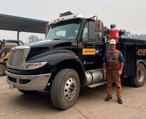
Peterson provides machine maintenance and repair using fully equipped field service trucks and factory-trained technicians. Our technicians are supported by an in-house team of technical communicators and factory-certified instructors.
Peterson opened for business on November 16, 1936. It has remained family-owned ever since.
Operator and Technician Training
Heavy equipment operator training is conducted on your jobsite with your machines, so the training is directly relevant to your equipment, operators, jobsites, and working conditions.
Heavy equipment technician training is offered through Peterson University, the same organization that trains Peterson technicians. Peterson University classes are held in San Leandro, California and Hillsboro, Oregon.
News Stories About Peterson In Susanville
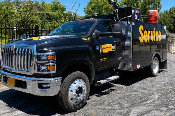
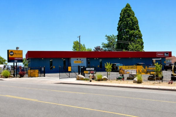
Photos of Peterson Cat and Cresco in Susanville, California
 WARNING